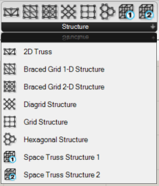
These components create lines (curves) and nodes (points) representing structural trusses, grids, and space trusses.
Description
Appearance
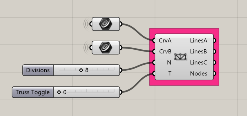
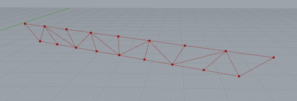
2D Truss
Creates a 2D truss using a set of edge curves.
Input:
- Two lists of curves (“CrvA” and “CrvB”) representing the length of either the op or bottom cord of a truss
- The desired number of divisions along the truss (N).
- The truss configuration type (T).
- “0” = a Two-direction web,
- “1” = Single direction web,
- “2” = Reverse single direction web.
Returns:
- LinesA: a list of the top and bottom cords
- LinesB: a list of the diagonal webs
- LinesC: a list of the vertical/plumb webs
- Nodes: a list of the connection points (intersections of webs and cords)
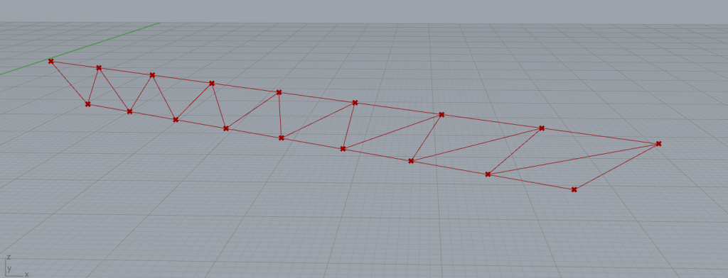
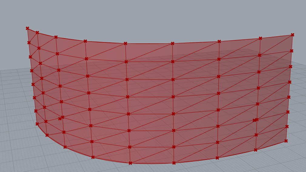
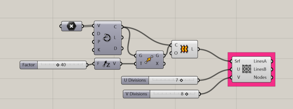
Braced Grid 1D Structure
Creates a single-direction braced grid on a given surface
Input:
- A list of surfaces
- A number indicating the number of divisions in the U-direction
- A number indicating the number of divisions in the V-direction
Results:
- Lines A: A list of curves that are parallel to the UV grid.
- Lines B: A list of curves that are diagonal to the UV grid, or in other words, the diagonal braces.
- Nodes: a list of the intersection points of Lines A and Lines B
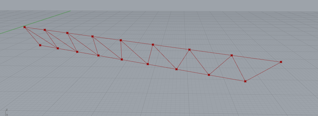
Braced Grid 1D Structure
Creates a two-directional braced grid on a given surface.
Input:
- A list of surfaces
- A number indicating the number of divisions in the U-direction
- A number indicating the number of divisions in the V-direction
Results:
- Lines A: A list of curves that are parallel to the UV grid.
- Lines B: A list of curves that are diagonal to the UV grid, or in other words, the diagonal braces.
- Nodes: a list of the intersection points of Lines A and Lines B
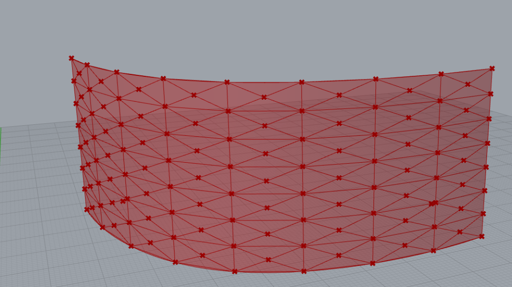
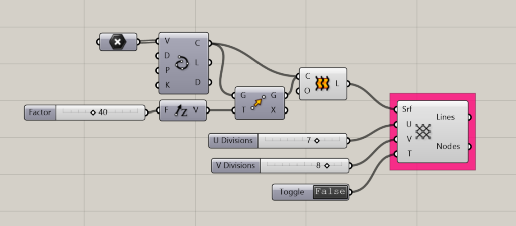
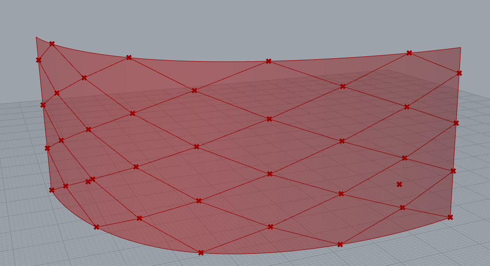
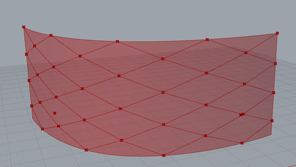
Diagrid Structure
Creates a diagrid structure on a given surface
Input:
- A list of surfaces
- A number indicating the number of divisions in the U-direction
- A number indicating the number of divisions in the V-direction
- A boolean toggle to set the division configuration type (T).
Returns:
- A list of the resulting lines
- A list of the resulting intersections as points
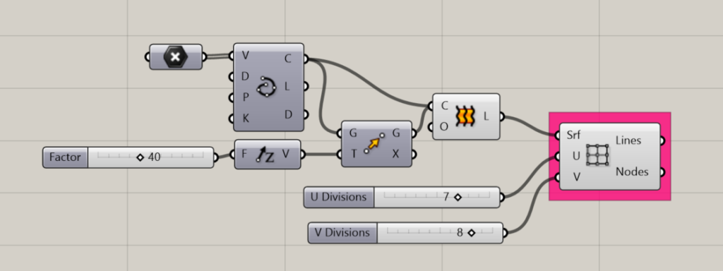
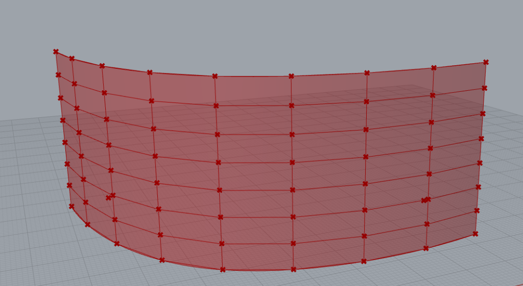
Grid Structure
Creates a grid structure along a surface
Input:
- A list of surfaces
- A number indicating the number of divisions in the U-direction
- A number indicating the number of divisions in the V-direction
Returns:
- A list of the resulting lines
- A list of the resulting intersections as points
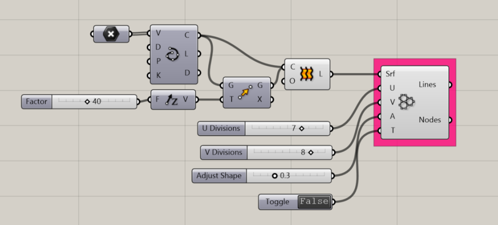
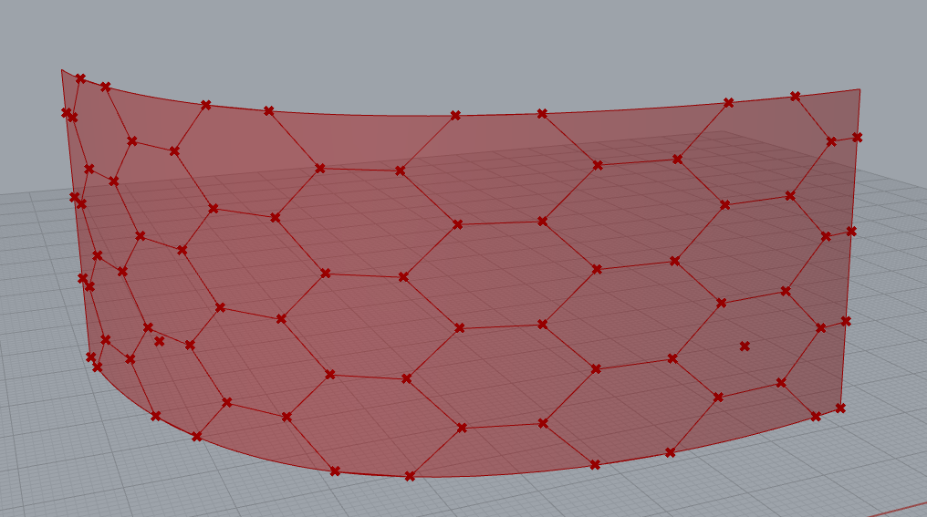
Hexagonal Structure
Creates a hexagonal structure on a surface.
Input:
- A list of surfaces
- A number indicating the number of divisions in the U-direction
- A number indicating the number of divisions in the V-direction
- An adjustment factor, to alter the shape of the hexagon
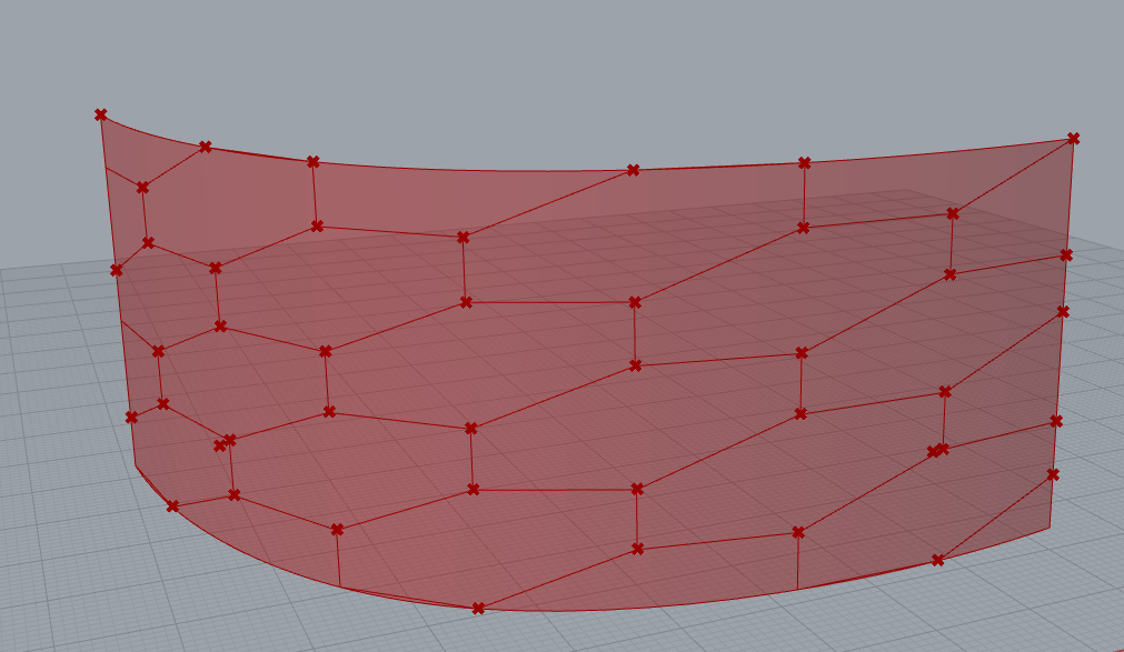
- A boolean toggle to set the division configuration type (T).
Returns:
- A list of the resulting lines
- A list of the resulting intersections as points
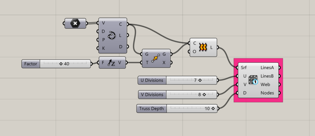
Space Truss Structure 1
Creates a space truss as an offset 3D grid along a surface.
Input:
- A list of surfaces representing the outer boundary of the space truss.
- A number indicating the number of divisions in the U-direction
- A number indicating the number of divisions in the V-direction
- A number to determine the offset distance, or in other words, the depth of the space frame.
Results:
- Lines A: The orthogonal grid along the outer boundary of the space frame
- Lines B: The orthogonal grid along the inner boundary of the space frame
- Web: The diagonal connecting members between the outer and inner orthogonal grids.
- Nodes: The intersection points between the Lines and the Web members.
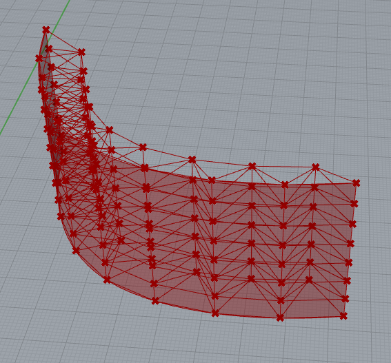
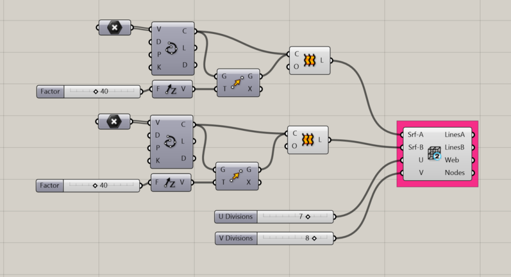
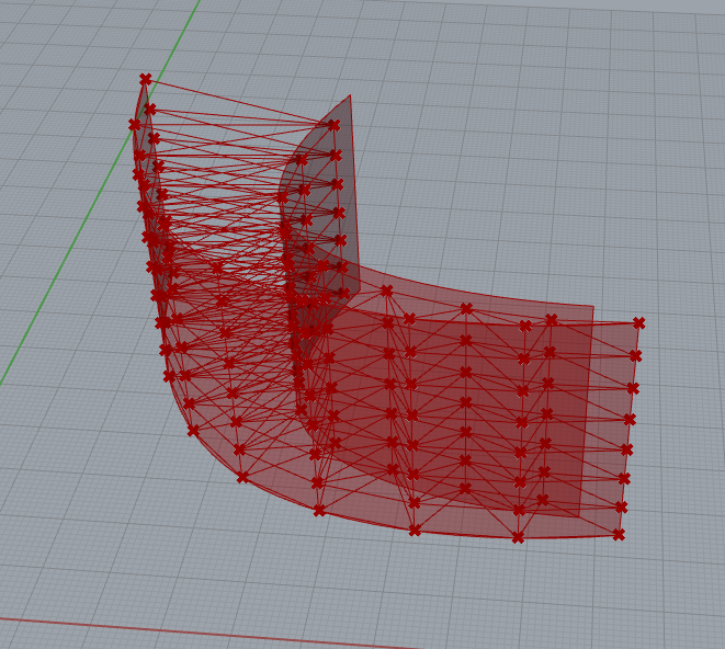
Space Truss Structure 2
Creates a space truss between two surfaces
Input:
- SrfA: A list of surfaces representing the outer boundary of the space truss.
- SrfB: A list of surfaces representing the inner boundary of the space truss
- A number indicating the number of divisions in the U-direction
- A number indicating the number of divisions in the V-direction
Results:
- Lines A: The orthogonal grid along the outer boundary of the space frame
- Lines B: The orthogonal grid along the inner boundary of the space frame
- Web: The diagonal connecting members between the outer and inner orthogonal grids.
- Nodes: The intersection points between the Lines and the Web members.