Conveyor Components
The Conveyor components for Grasshopper allow users to apply Conveyor categories to Rhino objects, create block definitions, and write files.
Important: Prior to attempting to use the Conveyor Grasshopper components, instantiate Conveyor in Rhino by running the command “Conveyor V4”.
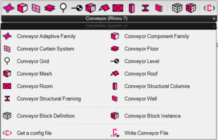
The Conveyor installer will add the Conveyor menu to Grasshopper. It includes the nodes as shown in the image on the left. See the descriptions below.
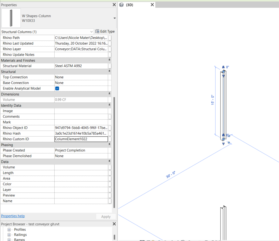
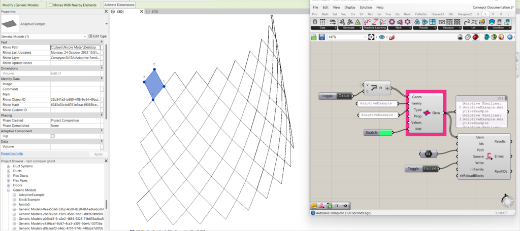
General tip: Refer to the Project Browser in Revit to verify Type and Family names.
Description
Appearance
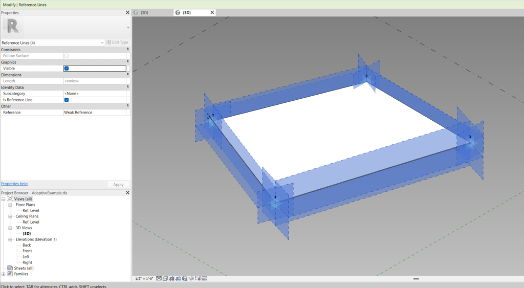
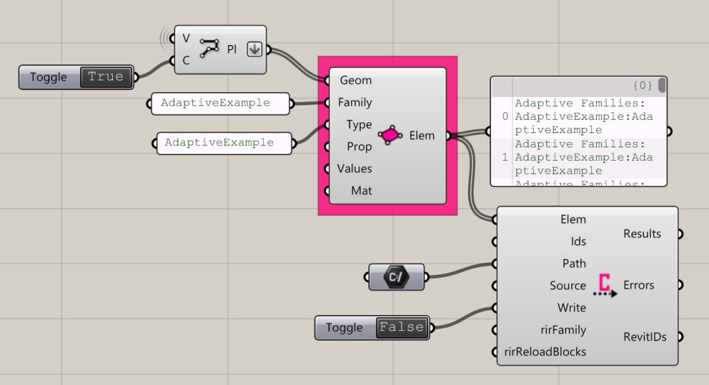
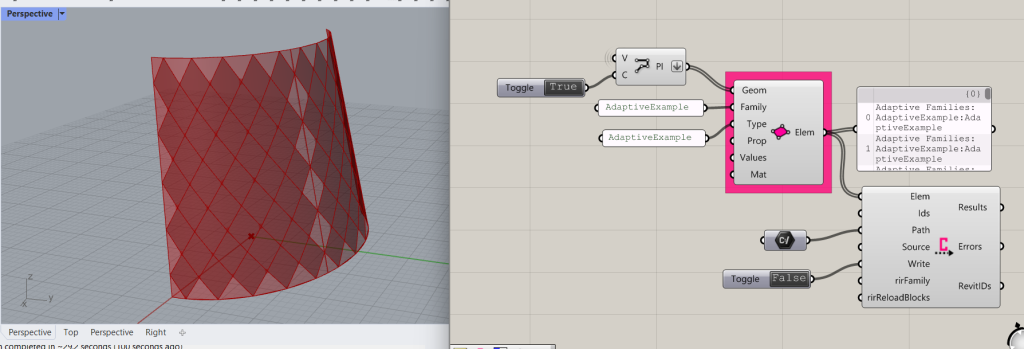
Conveyor Adaptive Family
Prior to using this component, ensure that an Adaptive Family has been loaded into Revit.
Input:
- A list of closed polylines with the number of vertices that correspond to the Adaptive Component family that will be used in Revit
- The Family name of the adaptive component in Revit
- The Type name of the adaptive component in Revit
- (Optional) The name of a Property to which a value will be written
- (Optional, unless a Property is input) A Value to write to the specified Property.
- (Optional) A shader parameter to control the object’s appearance in Rhino. It will not affect the object’s appearance in Revit.
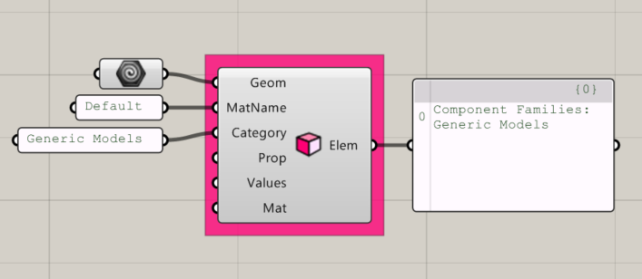
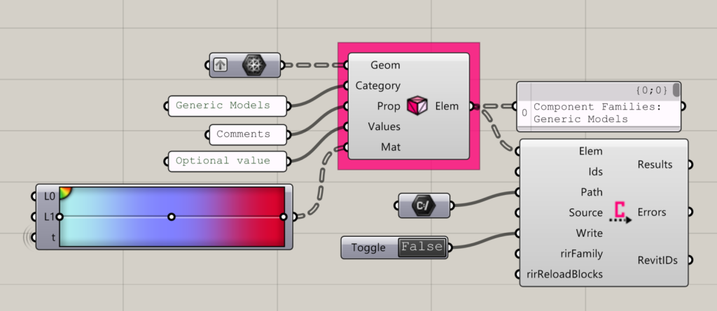
Conveyor Component Family
Creates a Conveyor Component Family Element
Input:
- A list of Geometry elements
- A Material Name for the element, matching an existing Revit material name, for the object to inherit when it is brought into Revit. This will not affect the element’s appearance in Rhino.
- A Revit Category (i.e. “Generic Models”)
- (Optional) The name of a Property to which a value will be written
- (Optional, unless a Property is input) A Value to write to the specified Property.
- (Optional) A shader parameter to control the object’s appearance in Rhino. It will not affect the object’s appearance in Revit.
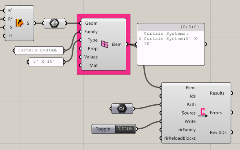
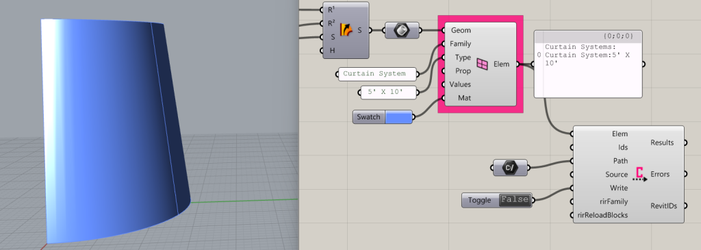
Conveyor Curtain System
Creates Conveyor Curtain System Elements
Input:
- A list of Geometry, as Breps, to create a curtain system from. Note: does not need to be panelized or faceted.
- A Family name, i.e. “Curtain System”
- A Type name that corresponds to one that exists in the Revit file for the specified Family.
- (Optional) A property or list of properties. These should already exist as properties in the Revit type.
- (Optional, unless Properties are input) A value or list of values that correspond with the Properties.
- (Optional) A list of shader parameter values. This will shade the elements in Rhino, but does not write the material in Revit. Note, the Revit material will be determined by the Curtain System family type’s material parameter.
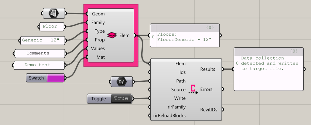
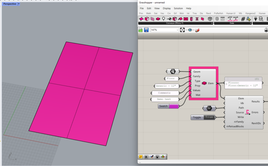
Conveyor Floor
Applies properties to a list of Surfaces to prepare objects to Convey to Rhino as Revit floors.
Input:
- A list of surfaces
- A family name (Accepts “Floor” or “Basic Floor”)
- The name of the family type. This should already exist in Revit and the spelling should match.
- (Optional) A property or list of properties. These should already exist as properties in the Revit type. In the example, Comments is used.
- (Optional, unless Properties are input) A value or list of values that correspond with the Properties. The value type should match the expected formatting for the Type of Property (e.g.: a Length property would expect an integer).
- (Optional) A list of shader parameter values. This will shade the elements in Rhino, but does not write the material in Revit. Note, the Revit material will be determined by the floor family type’s material parameter.
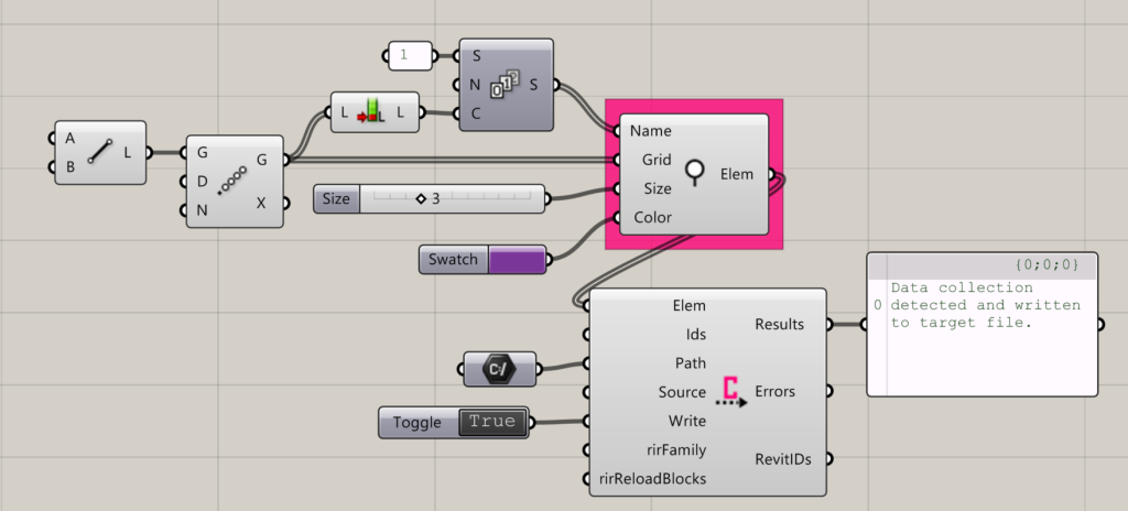
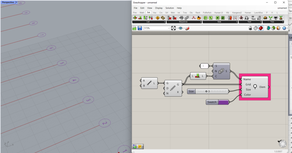
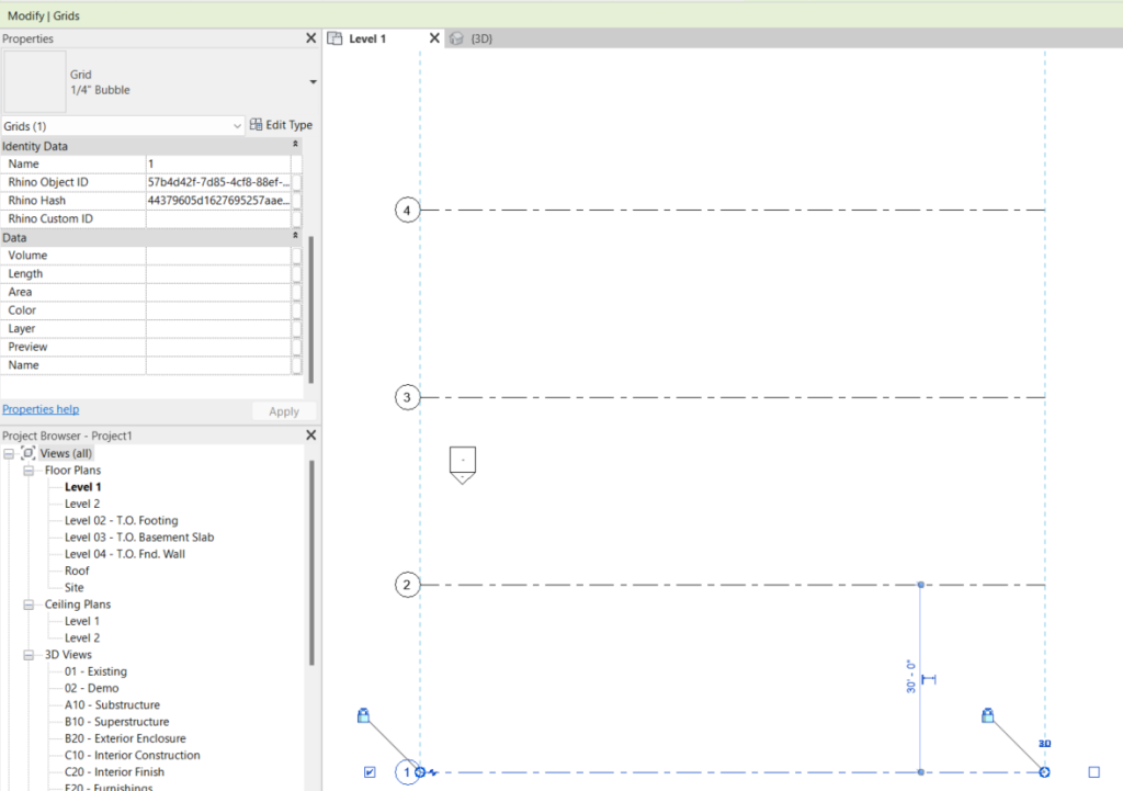
Conveyor Grid
Creates grids, names them, and returns a list of Conveyor Elements to be sent to Revit.
Input:
- A list of Names to give to the Grids
- A list of lines representing the grids and their extents
- (Optional) A number to set the relative size of the Grid bubble as it appears in Rhino. This does not change the size of the Grid bubble or text in Revit.
- (Optional) A color to set the Grid Bubble’s appearance in Rhino. This does not change the Grid bubble’s appearance in Revit.
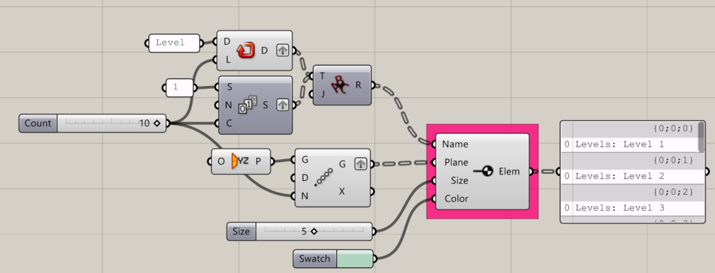
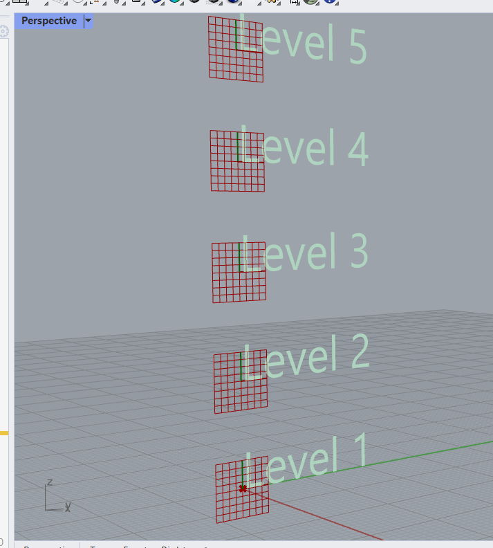
Conveyor Level
Creates levels at the specified planes.
Input:
- A list of names to assign to the layers. Tip: Check that the tree structure of your names list matches that of the Planes list
- A list of planes where layers will be added. The actual location of the layer will be at the origin point of the plane. The orientation of the text labels that appear in Rhino will match the orientation of the plane, so XY oriented planes will have text that reads in the XY orientation, and so forth.
- (Optional) A list of numbers to set the size of the text in Rhino. This will not affect the size of the text in Revit.
- (Optional) A list of colors to set the color of the text in Rhino. This will not affect the color of the text in Revit.
Conveyor Mesh
Creates Conveyor Elements for the specified meshes.
Input:
- A list of Mesh geometry
- A Category (e.g.: Generic Models)
- (Optional) Properties to write to the mesh
- (Optional unless a Property name is input) Values to assign to the properties
- (Optional) A list of colors to set the mesh’s appearance in Rhino.
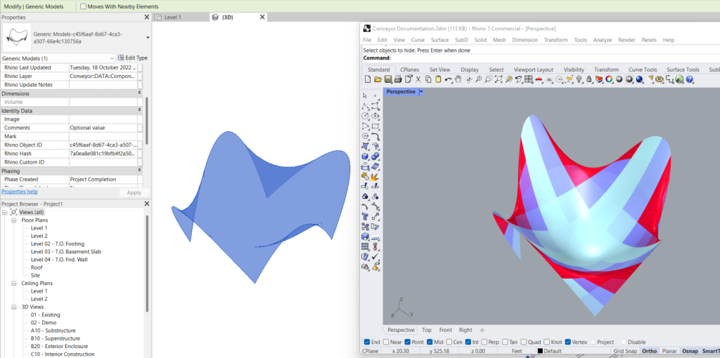
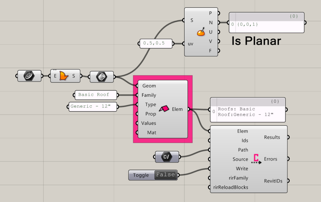
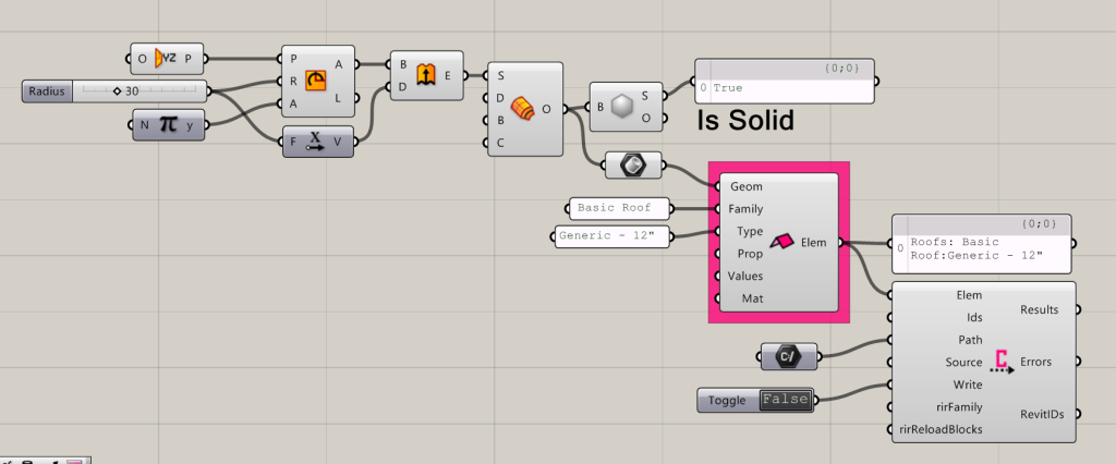
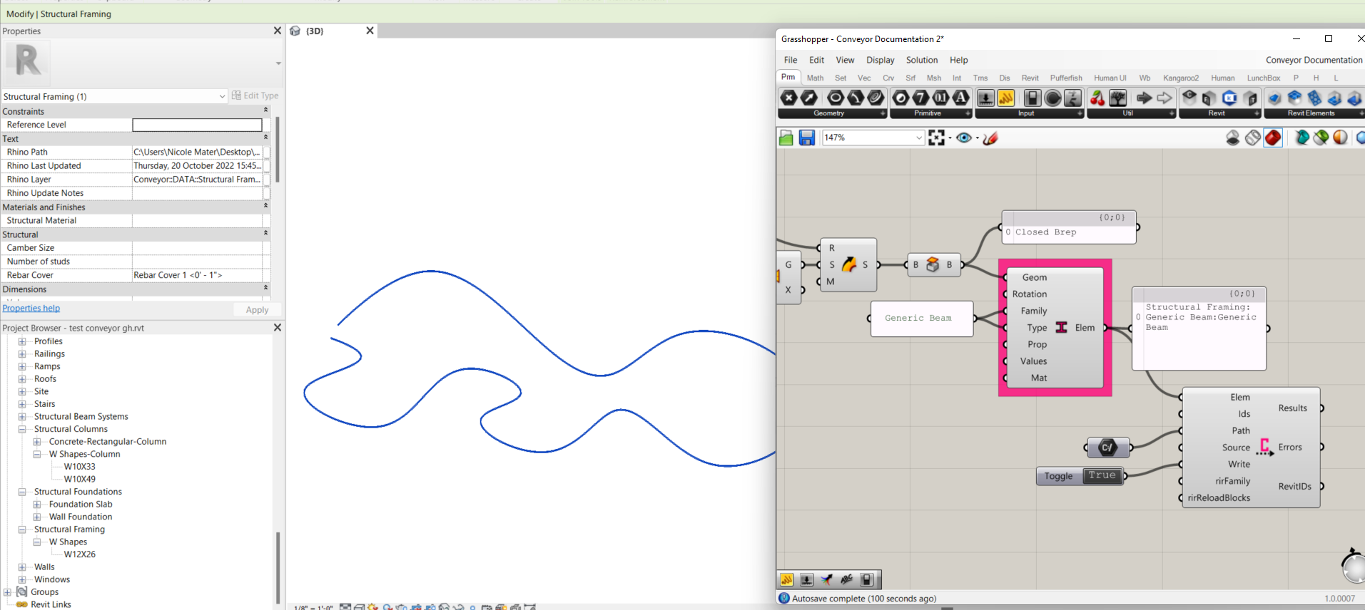
Conveyor Roof
Creates Conveyor Elements for the specified surfaces.
Learn more about converting Roofs here…
Input:
- A list of either…
- Surfaces as Breps that are in plane with a level, or in other words, flat surfaces along an XY plane. These may have holes cut into them or have trimmed edges.
- OR, closed solids as Breps. Note that inputting closed solids will convert roofs as Direct Shapes.
- A family name, matching one that exists in Revit
- A family type, corresponding to one that exists in Revit for the named family
- (Optional) A property that exists for the specified family type in Revit, to write a value to
- (Optional) A value to write to the specified property
- (Optional) A shader parameter to change the object’s appearance in Rhino. Will not change the converted objects appearance in Revit.
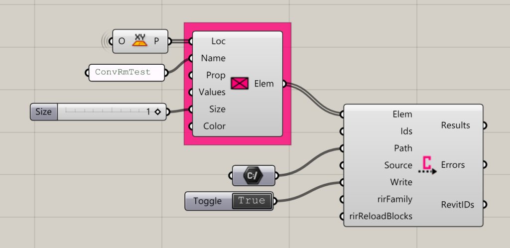
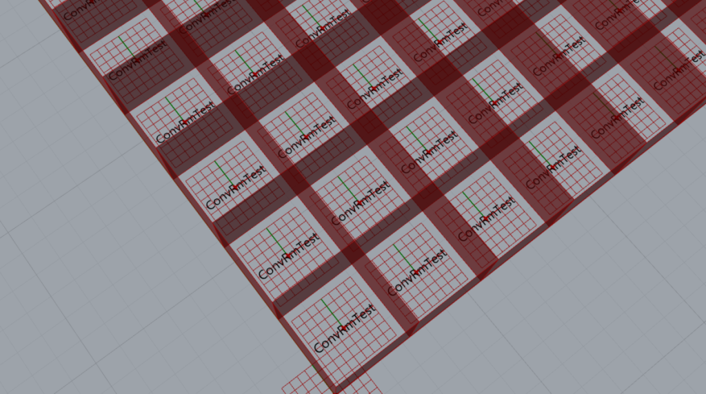
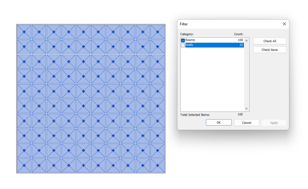
Conveyor Room
Creates Conveyor Room Elements with a list of Room locations, names, and properties
Pre-requisite:
- Walls or other room boundaries must be in place in Revit prior to using this component.
Input:
- A list of planes, where the origin of each plane is in the center of the room(s) that will be created.
- A list of names to give to the rooms. Note that the rooms will automatically be numbered based on their list order in Grasshopper and the next available room number in Revit.
- (Optional) A Property name that you wish to write a value to, that already exists for the Family Type you are specifying
- (Optional) A value or list of values to write to the specified Property
- (Optional) A number parameter to customize the size of the text for the Room Name in Rhino. This will not change the Room Tag appearance in Revit.
- (Optional) A shader parameter to customize the appearance of the Room Name in Rhino. This will not change the Room Tag appearance in Revit.
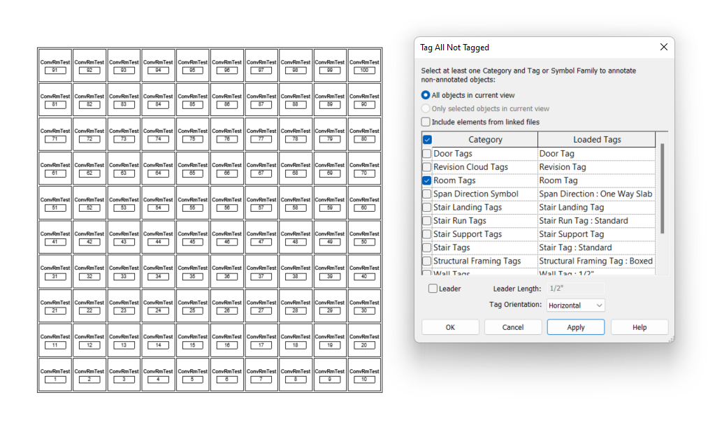
Tip: Once rooms have been sent to Revit, use the “Tag All Not Tagged” function in Revit to quickly tag the rooms.
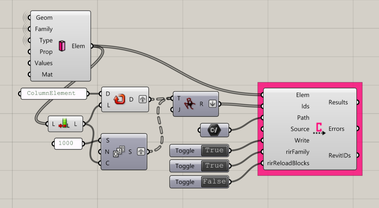
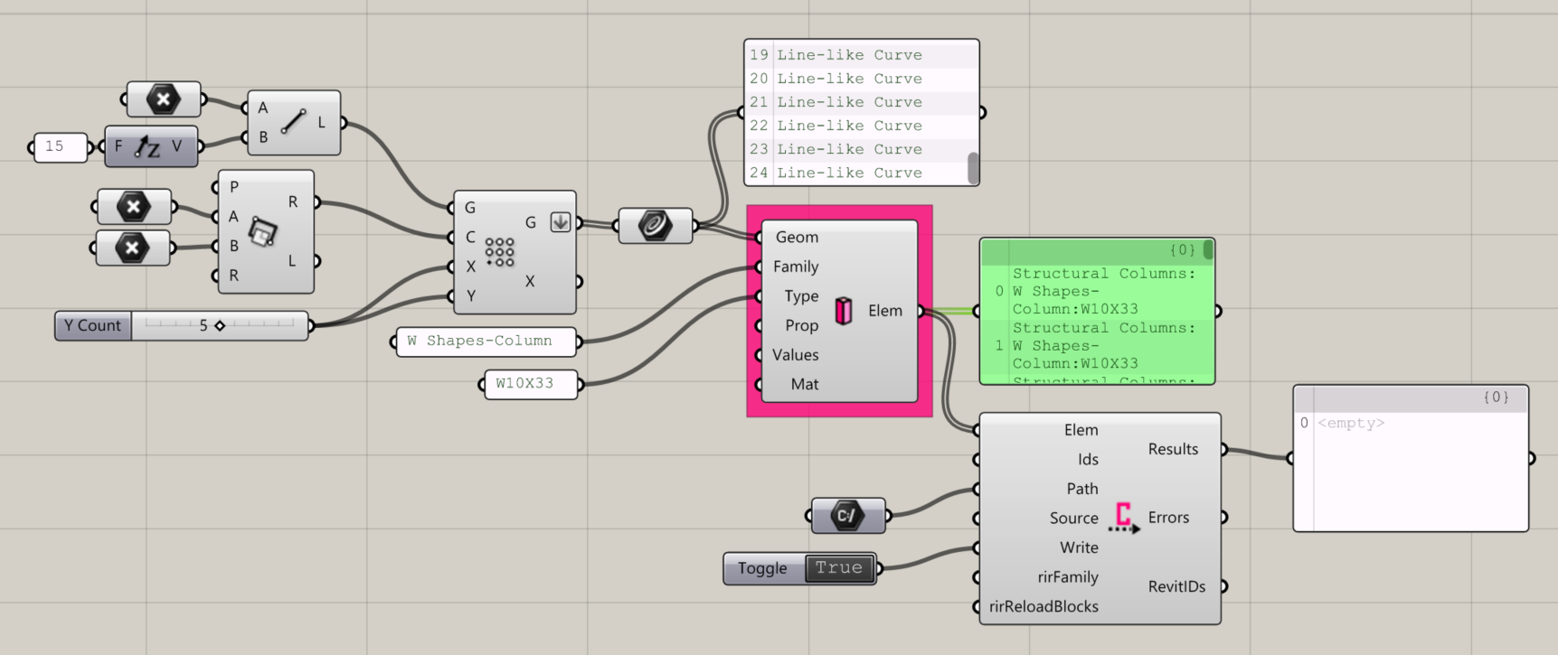
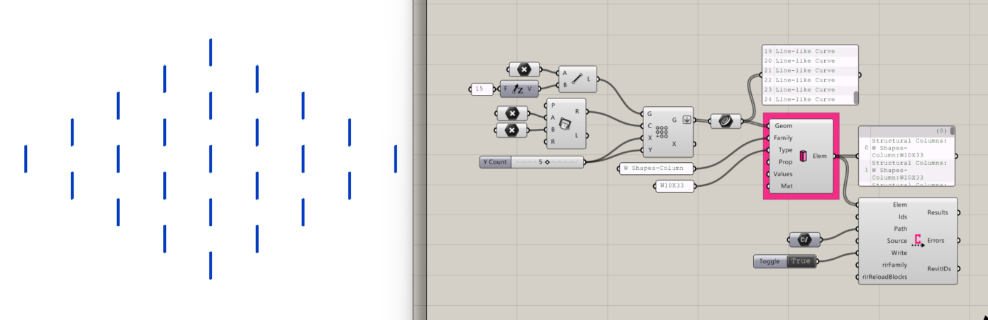
Conveyor Structural Columns
Creates Conveyor Structural Columns Elements for the specified curves
Input:
- A list of either…
- line-like curves (Tip: Pass line elements through a Curve parameter)
- OR, closed Breps to convert as Direct Shapes
- A Family name, matching one that already exists in your Revit file under Structural Framing
- To convert a brep as a Direct Shape, use “Generic Column”
- A family Type name that already exists in your Revit file corresponding to the Family name
- To convert a brep as a Direct Shape, use “Generic Column”
- (Optional) A Property name that you wish to write a value to, that already exists for the Family Type you are specifying
- (Optional) A value to write to the Property
- (Optional) A shader parameter to customize the appearance of the elements in Rhino. This will not change the appearance of the objects in Revit.
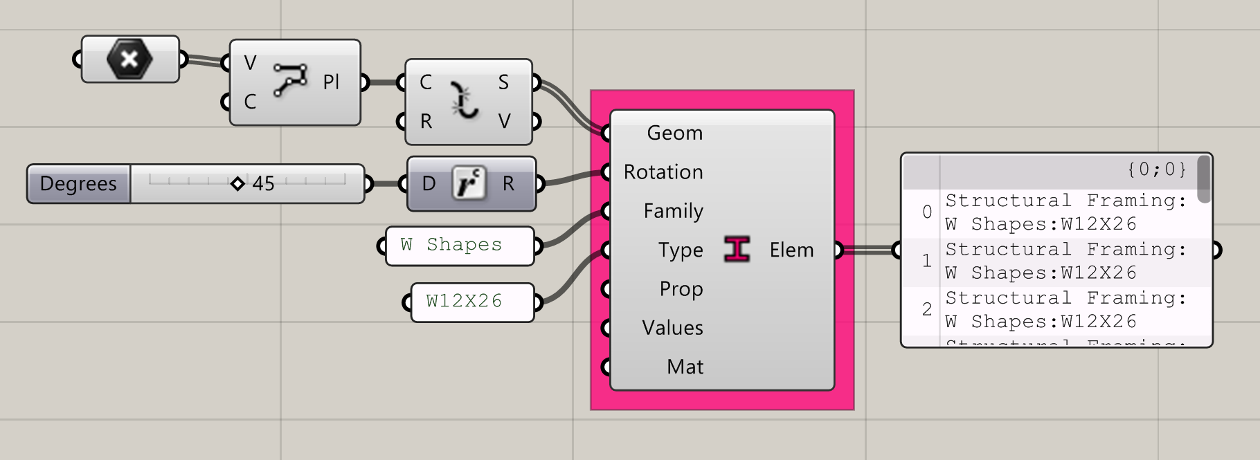
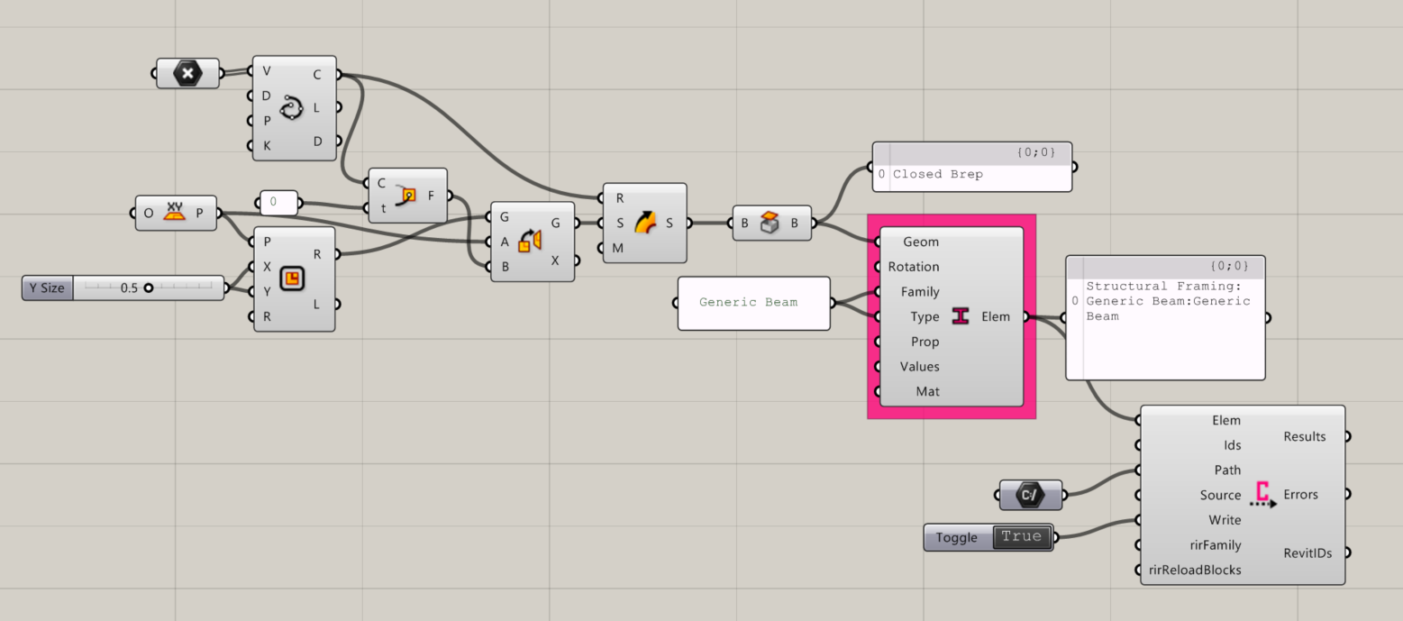
Conveyor Structural Framing
Creates Conveyor Structural Framing Elements for the specified curves.
- A list of either…
- line-like curves
- OR, closed breps to convert as Direct Shapes
- A Family name, matching one that already exists in your Revit file under Structural Framing
- To convert a brep as a Direct Shape, use “Generic Column” or “Generic Beam”
- A family Type name that already exists in your Revit file corresponding to the Family name
- To convert a brep as a Direct Shape, use “Generic Column” or “Generic Beam”
- (Optional) A Property name that you wish to write a value to, that already exists for the Family Type you are specifying
- (Optional) A value to write to the Property
- (Optional) A shader parameter to customize the appearance of the elements in Rhino. This will not change the appearance of the objects in Revit.
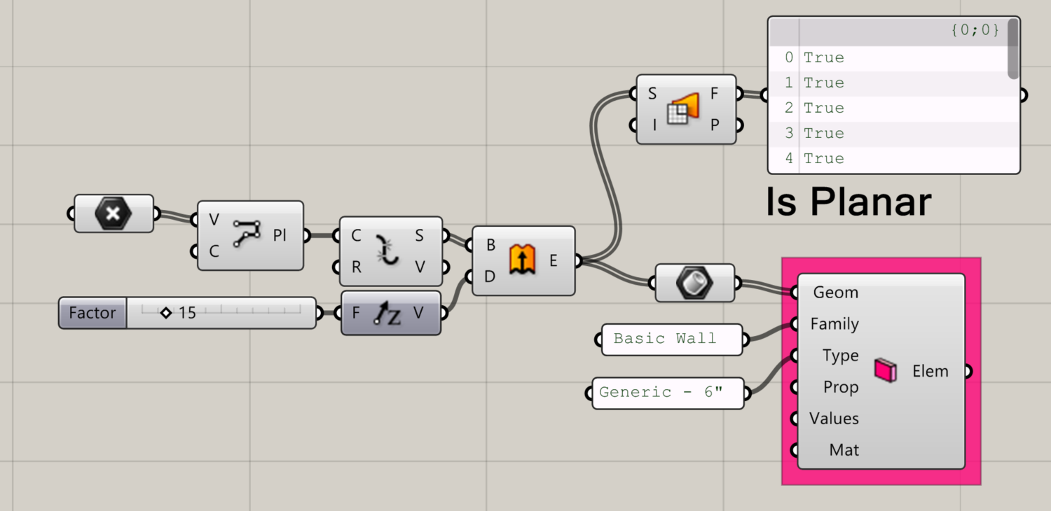
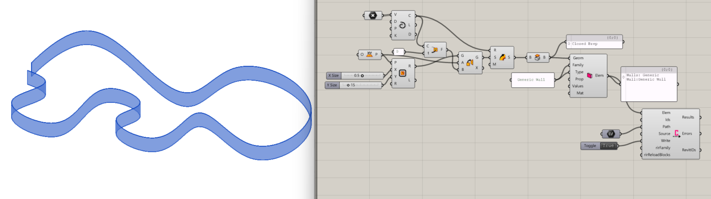
Conveyor Wall
Creates Conveyor Wall Elements for the specified planar surfaces or closed breps.
Input:
- A list of Geometry, either
- Vertical surfaces, oriented in the YZ or XZ plane
- Closed Breps, to convert to Revit as Direct Shapes
- A Family name, matching one that already exists in your Revit file
- To convert a Brep as a Direct Shape, use “Generic Wall”
- A family Type name that already exists in your Revit file corresponding to the Family name
- To convert a Brep as a Direct Shape, use “Generic Wall”
- (Optional) A Property name that you wish to write a value to, that already exists for the Family Type you are specifying
- (Optional) A value to write to the Property
- (Optional) A shader parameter to customize the appearance of the elements in Rhino. This will not change the appearance of the objects in Revit.
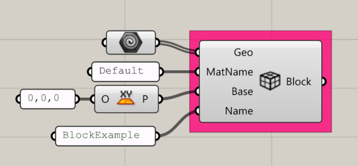
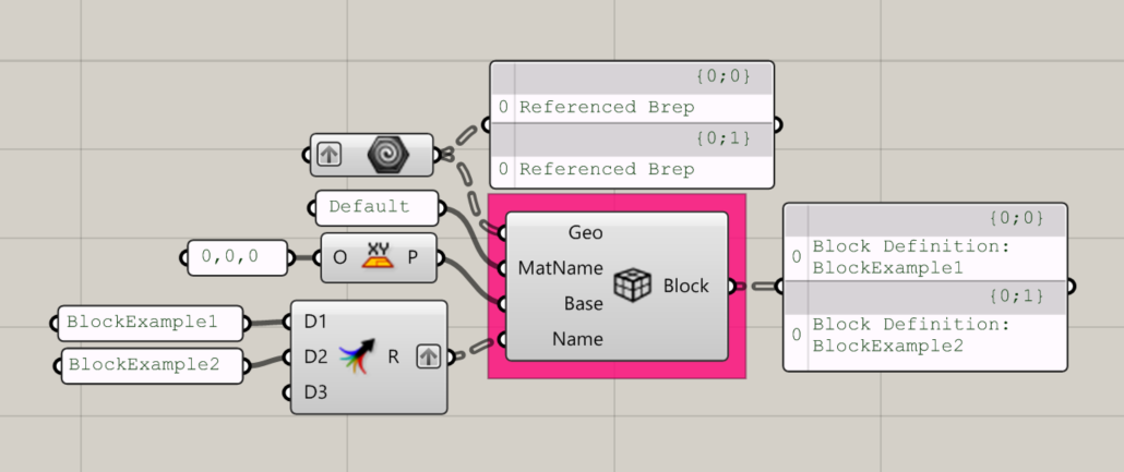
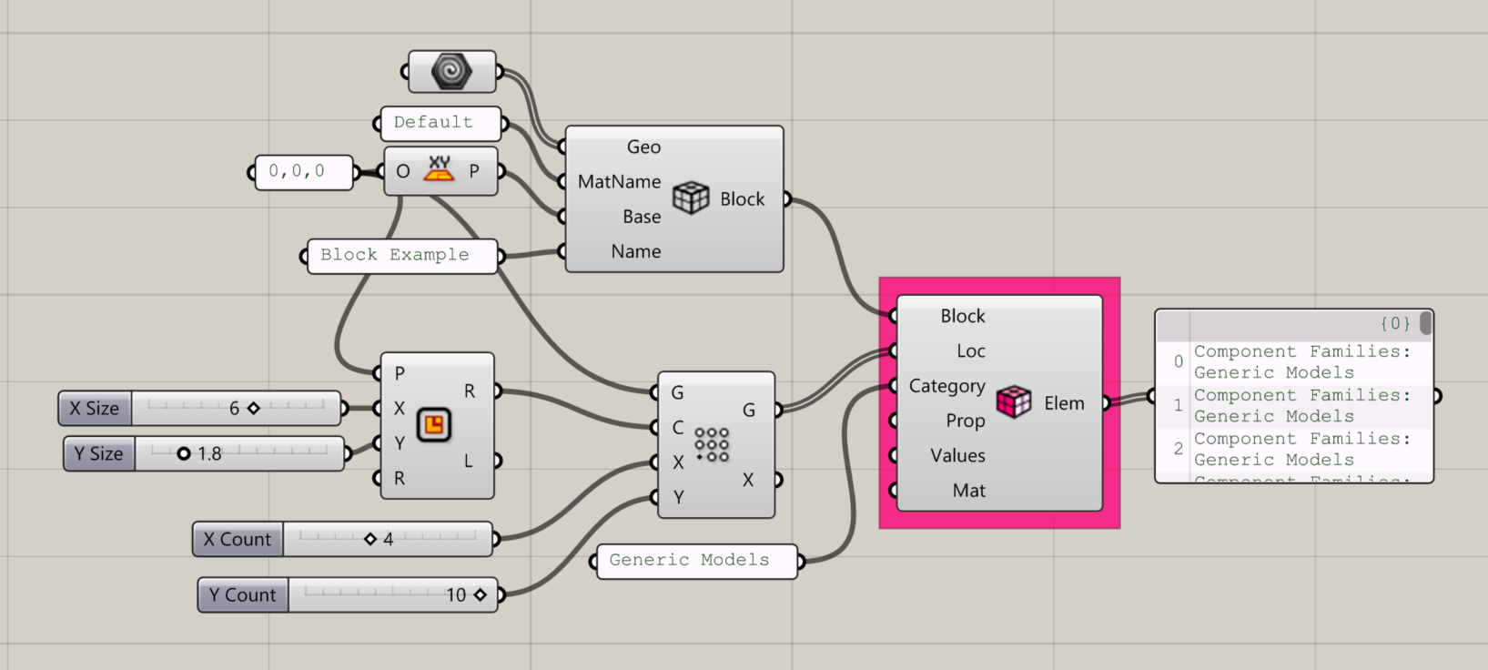
Conveyor Block Definition
Defines a block that can then be used to create a Conveyor Block Instance Element.
Input:
- A list of Geometric elements (Note: Pay attention to your data tree structure)
- A Revit material name, which the block will inherit when Conveyed to Revit.
- A Base/Insertion plane where the object should be instantiated. (Note: The geometry in this example is located at the point shown)
- A name for the block.
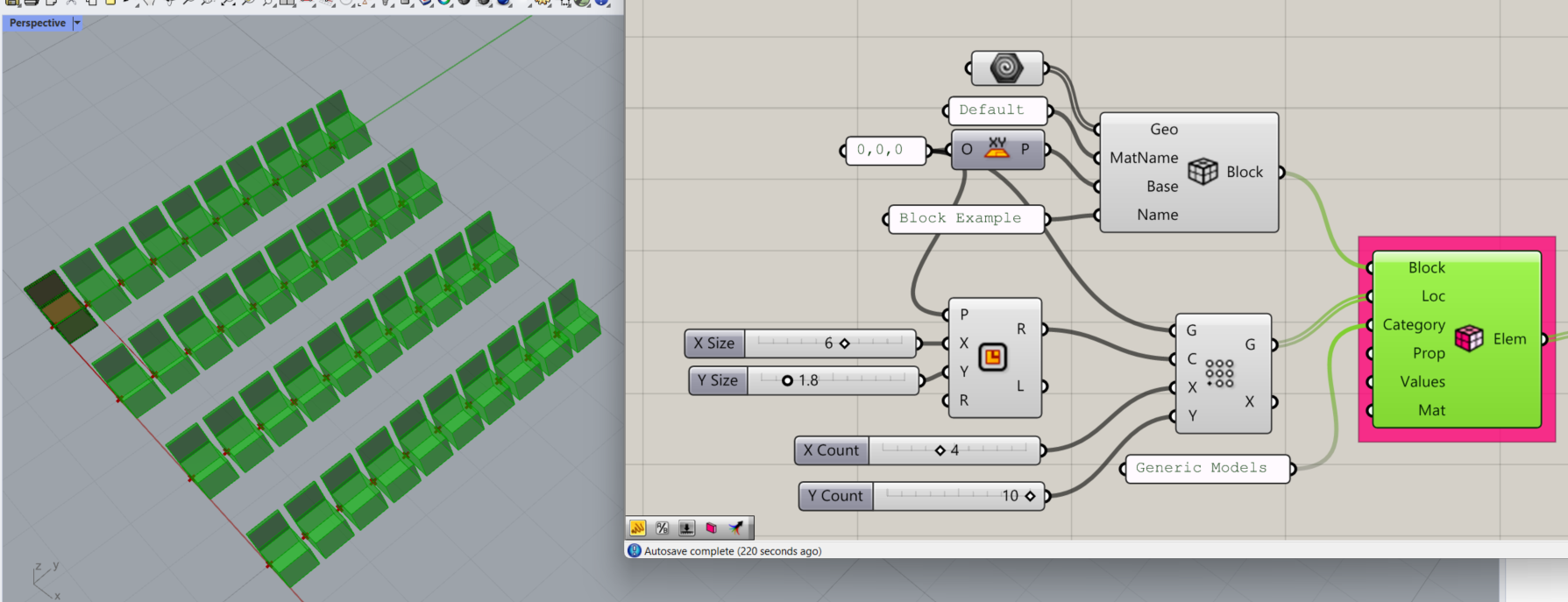
Conveyor Block Instance
Creates Conveyor Block Instance Elements using a defined block and instantiating it at the specified insertion points.
Input:
- A defined block
- A list of locations (points) where the blocks will be instantiated
- The Revit category to associate with the Conveyor Element(s)
- (Optional) Property to write a value to
- (Optional) Value to write to the specified Property
- (Optional) Shader parameter to set the element’s appearance in Rhino. This will not affect the object’s appearance in Revit.
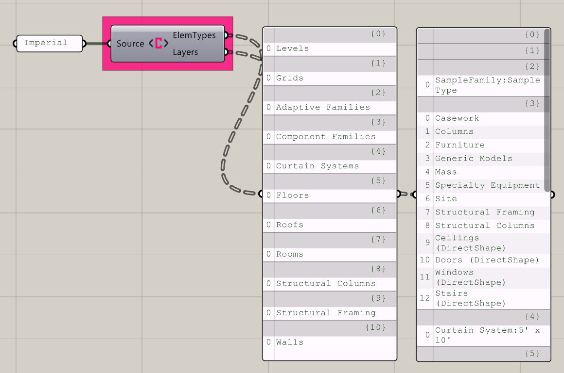
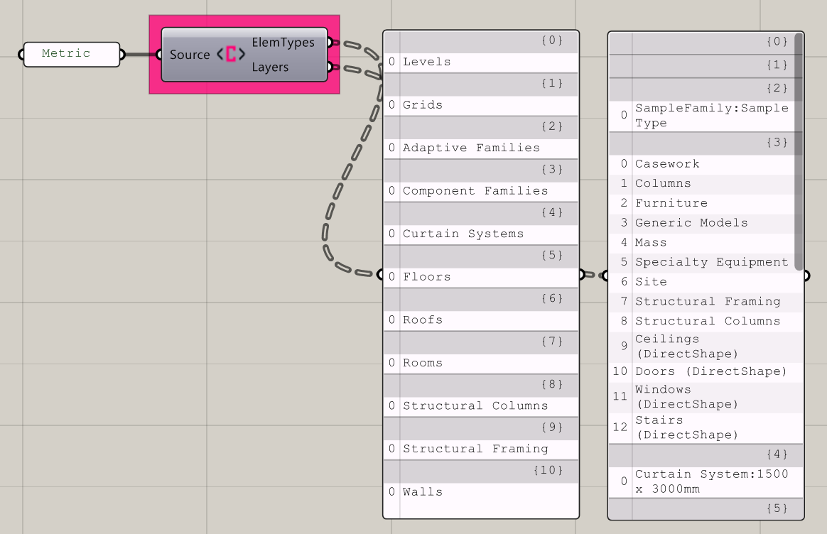
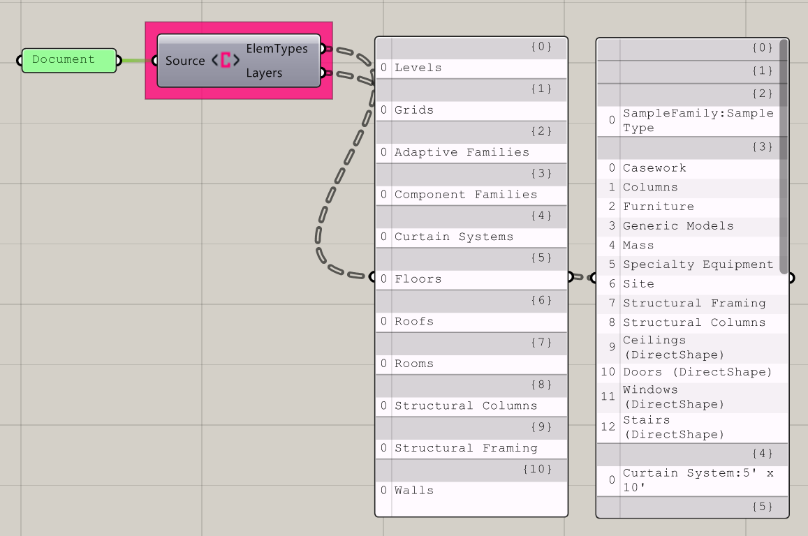
Get a config file
Returns a list of the Element Types and corresponding layers available for the given source.
Input:
- One of the following source types:
- Either “Imperial” (the default) or “Metric”, which will return standard Conveyor settings in either Imperial or Metric units.
- “Document”, for the types and layers available for the active document/session.
- A file path, for a custom layer config file
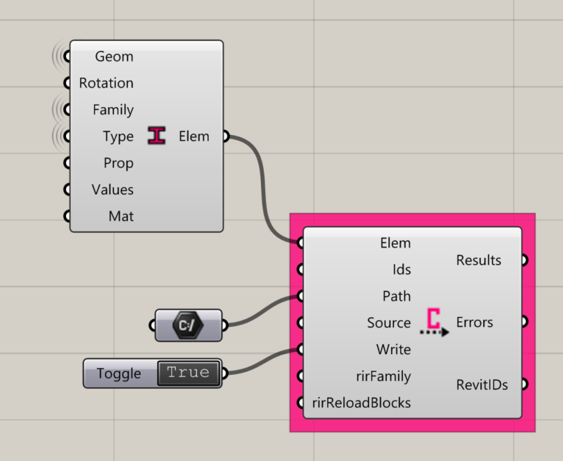
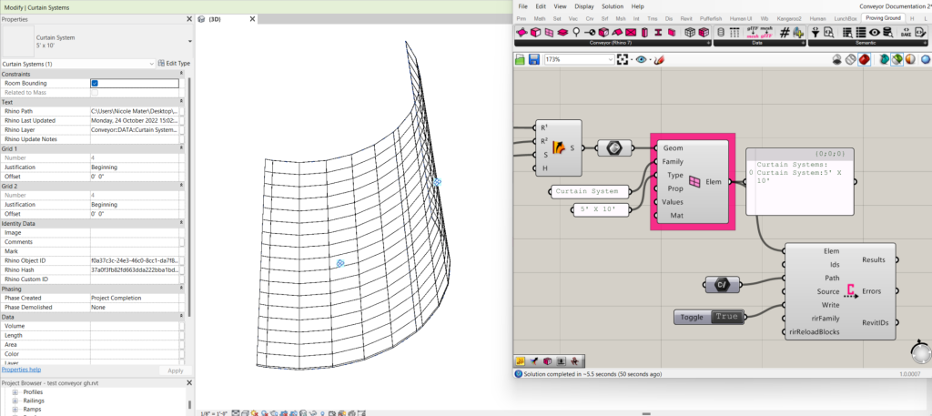
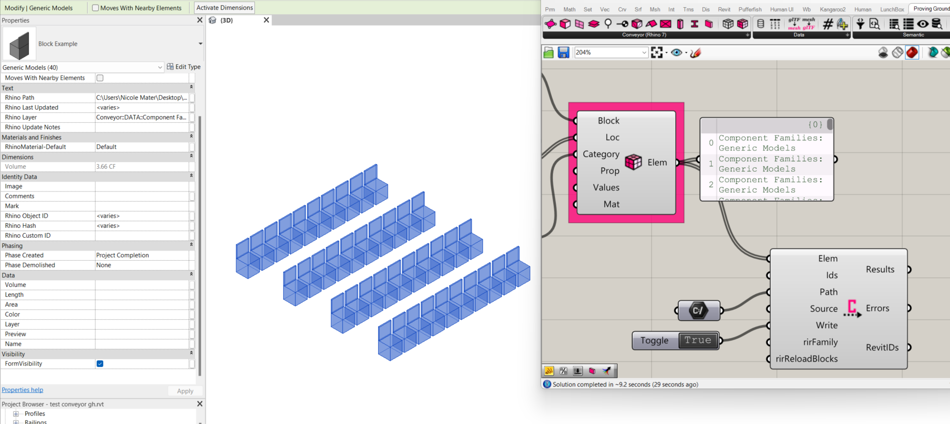
Write Conveyor File
Creates a temporary Rhino file at the specified file path (destination), which then sends the Conveyor Elements to Revit. Note: To be used in a Rhino instance that is open using Revit’s Rhino.Inside.Revit.
Input:
- A list of Elements from one or more Conveyor Elements components.
- (Optional) A list of IDs to assign to the Conveyor elements. Should be unique for each element.
- A file path to set the destination for the Conveyor file. Enter in a local file destination with a .3dm suffix. (Example: “C:\Users\UserName\Desktop\conveystruc.3dm”)
- (Optional) Enter “Imperial” or “Metric” to set the source for the Conveyor file. “Imperial” is default.
- A boolean toggle to execute.
- (Optional) A boolean toggle to indicate Family/Type or Direct Shape. Default is “True”, which is Family Type. Set to “False” for Direct Shape.
- (Optional) A boolean toggle to set whether objects will be overridden.